Intellectual Home
This is an incredibly pompous title, but bear with me. It’s a fun story about an old-timey telephone. I have several lights plugged into wall sockets in the living room, and while the ritual of turning them on and off one by one has its own charm, I decided it was time to centralize control. The end goal: a rotary phone that turns the lights on and off when certain digits are dialled.
Note that this post has been sitting around as a draft for literally years, so things might be a bit out of date.
On the light control side, I used this pack of 4 ZooZee smart plugs. These are not great for customization out of the box, and probably phone home and eat your household pets, but they can be readily flashed with the open-source Tasmota firmware. This can even be done without cracking them open, courtesy of Tuya-Convert. I had success using a Kali Linux live USB environment to run this. Once they are flashed, they respond to MQTT commands, which can be managed using Home Assistant. I’ve also had success just buying them with Tasmota already flashed. (No affiliation with any of these products - just wanted to report what I used.)
I may write up the full process for setting up Home Assistant with MQTT-based smart plugs later. This post just covers the phone-to-MQTT section, which I think is more interesting anyway. The summary is that the phone provides an MQTT sensor value between 0 and 9. On changes to the sensor value, the smart plugs can be toggled using an automation.
I also won’t be showing full code listings below, but the full source code for this project is available on GitLab.
Requirements
Parts
- A rotary phone of unknown provenance
- NodeMCU (ESP8266)
- MicroUSB cable and charger
Tools/Supplies
- Soldering iron + solder
- Electrical tape
- Screwdriver
Breadboarding
I got this rotary phone from a guy on Craigslist a couple of years ago. I think I paid $20 for it, which is sort of a surprising price. I’ve seen rotary phones go for close to $100 in those fancy vintage stores in the hipster part of town, and then I also get the idea that people routinely throw them out because they’re old technology. The phone is labelled as being property of BC Tel, but I don’t imagine Telus is keen to have these returned to them!
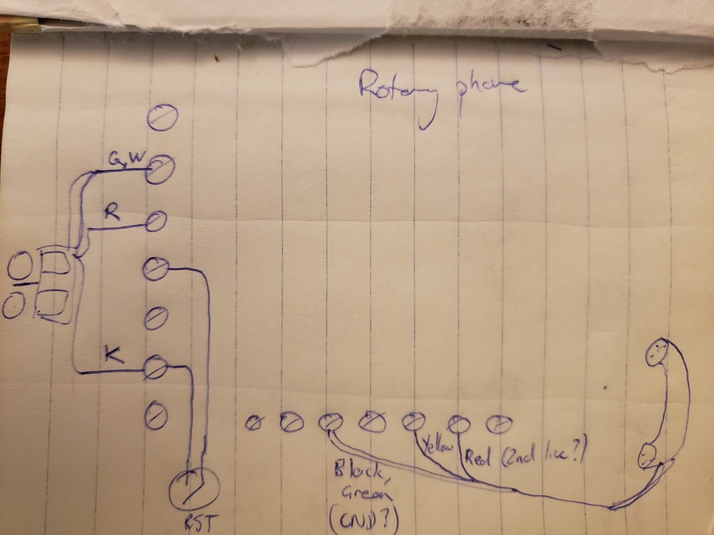
After examining the phone and playing with the dial a bit, the next step was to try and communicate with it. I initially wanted to only interface through the phone line. Unfortunately, the combined pulse and headset signal proved to be a bit too noisy, and I was curious, so I decided to open the phone up and connect directly to the dial and headset.
The headset has 4 wires leading out of it, but it looks like only 2 of these are used. I suspect the second pair is for connecting a second line. In any case, the mic and speaker are on the same loop, and it’s simply a matter of hooking up standard analog audio output to play a sound on the speaker.
As wired originally, the rotary dial is on the same circuit as the headset. I found that connecting the dial directly to the NodeMCU is a lot simpler. While the headset itself is out of the circuit now, the hook on which the headset rests still acts as an override switch. I added a pull-up resistor, which keeps the input to the pin high when the phone is on the hook.
Programming the ESP8266
First, the hardware: a NodeMCU dev board. This board uses an ESP8266 chip, which is incidentally the same chip as that found inside the smart switches used in this project. The ESP8266 is a microcontroller with onboard WiFi, which is perfect for this project. The board was originally designed to be programmed in Lua, but it is capable of running Arduino. This seems to be the most common way to use it.
As an aside, I have an extremely negative impression of Lua. This is entirely due to having had the misfortune of being in a class at university with an incredibly obnoxious person who happened to be a Lua enthusiast. I recognize that this is absurd and illogical, but until I have a need to use Lua, and find out that it’s a perfectly pleasant and useful language, I don’t imagine I’ll shake this perception. At this point, one could muse on fearing the unknown, but I am just blogging about phoning your lightbulbs, so I will refrain.
I won’t go into detail about basic setup, because others have already done so. It required installing the Arduino toolkit (SDK?), and I opted to use PlatformIO in VS Code as my development environment.
The structure of the Arduino sketch is two functions: setup() and loop().
setup() is called first, and is only called once. After that, loop() is
called repeatedly.
Processing the dialled digits
At this point, I started experimenting with parsing the dial signal. Initially, I looked into using interrupts to react to a change of state on the pin, but this proved to be completely unreliable. Eventually, I settled on a simple loop to read the state of the pin, and tally up the dials.
The first step is just to set up the pin for reading. We also initialize the serial console so that we can print messages. The specific device I bought doesn’t allow for serial communication rates higher than 9600 bps.
const int PHONE_PORT = D1;
int lastDialled;

void setup() {
    Serial.begin(9600);

    lastDialled = -1;
    pinMode(PHONE_PORT, INPUT_PULLUP);
}
Now, in each loop(), I can read the state of the dial:
void loop(void) {
    int state = digitalRead(PHONE_PORT);
    Serial.println(state);
}
Great! So now we’re talking to the device! We could start by incrementing a counter every time there’s a state change, but we wouldn’t know when a digit is finished dialling. When making a call on a rotary phone, the slight pause between each series of pulses generated by the dial is enough to distinguish between digits. So, we set a timer and check how much time has elapsed since the state last changed:
//...
const ulong READ_LOOP_TIME = 10;
const uint16 LOOP_TIME = 1000;
//...

void loop(void) {
    static ulong lastChangedTime = millis();
    static int oldState = digitalRead(PHONE_PORT);

    if (state != oldState) {
        // Only increment on the rising edge of the pulse
        digit += (state == HIGH) ? 1 : 0;
        lastChangedTime = millis();
    }
    oldState = state;

    // This sets the sampling rate - no need to check the state more frequently
    delay(READ_LOOP_TIME);

    // If it's been longer than a second, we assume the pulse train is finished
    // and interpret the counter as a dialled digit
    if (millis() - lastChangedTime > LOOP_TIME) {
        dialled = parseDigit(digit);
        if (dialled > -1) {
            Serial.printf("Dialled %d\n", dialled);
            lastDialled = dialled;
        }
        digit = 0;
    }
}
Network connection
The rotary dial side is now working. Next, we need to get on WiFi:
bool configureWifi() {
  String ap = "myaccesspointssid";
  String key = "mytopsecretpassword";

  WiFi.begin(ap.c_str(), key.c_str());

  Serial.println("Connecting ...");

  while (WiFi.status() != WL_CONNECTED) {
    delay(250);
    Serial.print('.');
  }
  Serial.println('\n');

  Serial.print("Connected to ");
  Serial.println(WiFi.SSID());

  Serial.print("IP address:\t");
  Serial.println(WiFi.localIP());

  server.begin();

  return 0;
}
Once that is done, we connect to MQTT, so we can send the dialled digit to Home Assistant:
struct MQTTDetails {
  String server;
  uint16_t port;
  String topic;
};

MQTTDetails mqttDetails;

bool connectMqtt() {
  mqttDetails.server = "servername";
  mqttDetails.port = 1883;
  mqttDetails.topic = "homeassistant/rotary/state";

  if (mqtt.connected()) {
    return true;
  }
  if (mqtt.connect("rotary-phone")) {
    Serial.println("Successfully connected to MQTT");
    return true;
  }
  return false;
}
File-based configuration
Up to this point, the configuration values have been hard-coded. Let’s change that by storing a configuration file on the simple filesystem.
wifi_creds
myaccesspointssid
mytopsecretpassword
servername
1883
homeassistant/rotary/state
I don’t honestly remember precisely how I uploaded the file. At the time I did
this, SPIFFS was still the best filesystem to use. I see it’s now deprecated,
but here is the
documentation
on how to use it. In short, create a data folder next to src, place the file
inside, and run “Upload File System Image in PlatformIO.
To access the file on the controller:
File f = SPIFFS.open("/wifi_creds", "r");
if (!f) {
  Serial.println("Could not read wifi credentials");
  return false;
}

String ap = f.readStringUntil('\n');
String key = f.readStringUntil('\n');
mqttDetails.server = f.readStringUntil('\n');
mqttDetails.port = atoi(f.readStringUntil('\n').c_str());
mqttDetails.topic = f.readStringUntil('\n');
We can now proceed as before.
Music
The NodeMCU actually has about 4MB of storage, so there’s some room to play with. The phone’s dial is being put to good use, but the headset not so much. What if we could play some music to entertain the user?
The NodeMCU doesn’t have a sound card (i.e. a digital-analog converter) but
through the magic of pulse-width modulation, we can get some pretty
rough-sounding audio output nonetheless. There’s a very useful library for
ESP8266 sound generation called
ESP8266Audio, and we’ll make
use of the AudioOutputI2SNoDAC class to just play the audio directly over I2S!
The hold music is added to SPIFFS in the same way as the config file. The file
should be a mono WAV file, sampled at 8 kHz. I have a 9 second clip of “Music
Takes Me Up” by Mr.
Scruff
for my installation.
#include <AudioFileSourceSPIFFS.h>
#include <AudioGeneratorWAV.h>
#include <AudioOutputI2SNoDAC.h>

struct MusicPlay {
  AudioGeneratorWAV *wav;
  AudioFileSourceSPIFFS *file;
  AudioOutputI2SNoDAC *out;
};
MusicPlay music;

bool playHoldMusic() {
  delete music.file;
  delete music.out;
  delete music.wav;

  music.file = new AudioFileSourceSPIFFS("/holdmusic.wav");
  music.out = new AudioOutputI2SNoDAC();
  music.wav = new AudioGeneratorWAV();
  music.wav->begin(music.file, music.out);

  return true;
}
Putting it all together
You can see the full main.cpp file on GitLab.
Permanent installation
Setting this up to live permanently on a sideboard consisted of the following steps:
- Soldering the NodeMCU connections to the dial and headset
- Soldering the momentary push button on the lower right of the phone to the power of the controller for reset functionality
- Installing the NodeMCU securely (!) with electrical tape and foam
- Securing the USB cord instead of a phone cord
A note on ringers
I’ve seen several rotary phone modding tutorials online that really destroy the internals of the phone, but I wanted to keep my changes reversible. I think I’ve managed that, and I’ve kept this pinout so that I could reconnect everything I disconnected.
However, I removed the ringer so that I would have more space to install the controller chip, but it could definitely be left in if you’re brave enough to attempt the high voltage circuit required to make it ring. From various sources, it looks like you need at least 48V of AC. This might be a quick task for some readers, but I’m strictly a software professional, so I try to keep my hardware projects non-lethal. I ended up selling the ringer to a guy who said he used to build these for work some decades ago, and was going to use the ringer for some sort of alarm!